Product Library
Getting a GTC package from your manufacturers is the best way to quickly and accurately import your existing product. A package file contains a few xml files to define the product assortment, class hierarchy and the metadata about the package itself. Each product in the package has its own picture, family picture, data file P21, drawing DXF, basic model, and detail model STP. All of those files are packed in a ZIP file, enabling a productive data exchange model between cutting tool vendors and applications.
In this hands-on guide, we will use products in the demo package from Sandvik Coromant1. Please head to their website and grab yourself a copy.
Import GTC Package
After having the package file, follow these steps to import it to your product library.
- Move the mouse to the Sidebar, click Library ➔ Products to make it is the active document, then click the Import button on the Navigation Bar.
- In the import dialog, click Choose File and select the demo GTC package file. With a valid package, a table is displayed with package metadata as vendor name, acronym, the generic class hierarchy version as well as the vendor version.
- Press the Import button to confirm. Depending on the package size and your network speed, it might take a moment to attach the file. A successfully command will automatic close the dialog box, and a notification banner will tell you the import job has been started.
- When you see a red flashing dot in the right header, click it to open your Notification Center. The first message informs you that the import job has been completed. You can download the import report, mark it as read, or delete the message if you would like to.
After the import job is done, click Products icon on the sidebar again to refresh the page. Your products list now includes several dozen products.
Create custom products
Products can be created manually using their asset files. Those assets can be freely and easily downloaded from cutting tool manufacturer websites if they support the ISO 13399 standard. You will need to prepare the following asset files for each product.
- The data file or parameters file
P21. It describes the product parameters. Those parameters are needed to calculate cutting data or generate the tool data for CAM software. Tooling Metrics uses this file to parse the parameters, number, order code, barcode, connection codes and the operations. - The product picture and family picture. The family picture is the drawing with dimensions annotated by symbols, helping you interpret the product parameters.
- The asset files including the drawing
DXF, basic model or anti-collision model, and detailed modelSTPare used to visualize in the CAD Viewer, build Tool Assembly drawing and models, and get the coordinate systems.
To continue following this guide, you need to download the asset files for some products from Iscar and Tungaloy1 in the table bellow:
| Number | Designation | Class |
|---|---|---|
| 6154473 | SCD 035-014-060 ACP3N | DRLFSS: Cylindrical hole drill - solid - symmetrical point |
| 6154483 | SCD 045-017-060 ACP3N | DRLFSS: Cylindrical hole drill - solid - symmetrical point |
| 6154498 | SCD 060-020-060 ACP3N | DRLFSS: Cylindrical hole drill - solid - symmetrical point |
| 6154518 | SCD 080-029-080 ACP3N | DRLFSS: Cylindrical hole drill - solid - symmetrical point |
| 6154528 | SCD 090-035-100 ACP3N | DRLFSS: Cylindrical hole drill - solid - symmetrical point |
| 6154538 | SCD 100-035-100 ACP3N | DRLFSS: Cylindrical hole drill - solid - symmetrical point |
| 6154548 | SCD 110-040-120 ACP3N | DRLFSS: Cylindrical hole drill - solid - symmetrical point |
| 5621679 | ECF D-2/45-4C06 | MILCFS: Chamfer mill - front cutting - solid |
| 3376191 | ER16 SEAL 8 AA | ADPCL: Collet |
| 3375405 | ER20 SEAL 12 AA | ADPCL: Collet |
| 4530003 | BT40SEM27X45 | ADPRS: Adaptive item - Rotation symmetrical adaptor |
| 6874079 | TRRQ12M080B27.0R06 | MILFI: Face milling cutter - indexable |
| 6906572 | RQMT1204ENC8-MM AH3135 | INSCMIL: Milling insert |
Now make sure your active document is Products, then follow the steps bellow to create a custom product. Repeat for all products you have downloaded.
- Click the + New button in the navigation bar to start creating a new Product.
- In the new Product form, just select Tungaloy from the Manufacturer drop down, and its Class from the list.
- Attach the picture, family picture, data file, 2D drawing, and 3D models.
- Click Save & Sync from Data File
The command will read the content from data file and the step files you attached, then automatically parse and save all product attributes.
The attributes provided in the data file might missing and/or inaccurate. You can edit all product attributes you would like to, but not the ones in the parameters table yet.
Let’s view the detail product number 6874079. We notice that its operations and cutting reference points are both empty. We need to update that attribute by following these steps.
- Moving the mouse to the bottom toolbar and click Edit button.
- Mark the Face milling, Slot milling, Shoulder milling, and Copy milling checkbox in the Operations attribute.
- Click on the Cutting Reference Points(CRP) tab ➔ ⨁ button, to add a new CRP.
- In that new CRP row, set the Model to basic, named it CRP, and enter the X, Y, Z Pos at 0, 34, 0.
- Add other CRP with the Model is detailed, X, Y, Z Pos at 0, 34, -50. Now click Save to save the changes and close the edit product form.
You will notice that, we also need to update the Operations attribute for all drilling products which has been created.
At this point, we have the product library for those items we have in our inventory. We are going to use this library to create other documents we have in our machine shop. Let’s start with the Tool Library.
Tool Library
Build your first tool assembly
Follow these steps to build your first tool assembly.
- Click the + New button in the navigation bar to start creating a new tool assembly.
- In the new form that appears, enter the name as CAT40 Drill 3.5 ➔ click Save. You will be direct to the product detail view.
- Click the add product ⨁ button in the Structure tab. You will then see a products list in the right screen. Select the drill with designation SCD 035-014-060 ACP3N. This product should be appear in the first few rows. If not, you can easy find it by using the filters toolbar with it Manufacturer—Iscar and Operations—Drilling. Click the ⨁ button at the end of the row to confirm your selection.
- After the Assembler Viewer has completely loaded, it displays the drill model on the right. Move the mouse to the Assembly Builder on the left, then click Add to Machine side button on top of the drill product card.
- Once again, the Products List appears on the right, but with only products that can fit the drill we added before. Find the collet with designation 393.14-16 0600, then add it to our assembly.
- Repeat the steps ➃ and ➄ again to add the CAT 40 holder with designation AA3B14-40 16 067.
Now we have built a completed tool assembly for a 3.5 mm drill, help by a CAT 40 holder. The final step is to click on the Build Assets button in the bottom toolbar. While the building process is running, you can have a look at the Bill of Materials tab—consolidates all products by its quantity, and the Parameters tab—is the place to get the tool assembly parameters.
After the build process is completed, you can view the tool assembly drawing by clicking on the Drawing Viewer button on the right.
To view the tool assembly detailed model, click the 3D model icon in the CAD toolbar ➔ Detailed. The Assembly Viewer loads all product detailed models to render the detailed assembly. You can press the camera icon at the far right to command the CAD viewer capture the current image as the tool assembly picture.
Our next task is to calculate the cutting data for this drill, using the built-in Machining Calculator.
Calculate the cutting data
Head to the tool assembly tab-bar to activate the Cutting Data tab. A new Cutting Data form appears as Fig. 1, after you click on the add ⨁ button.
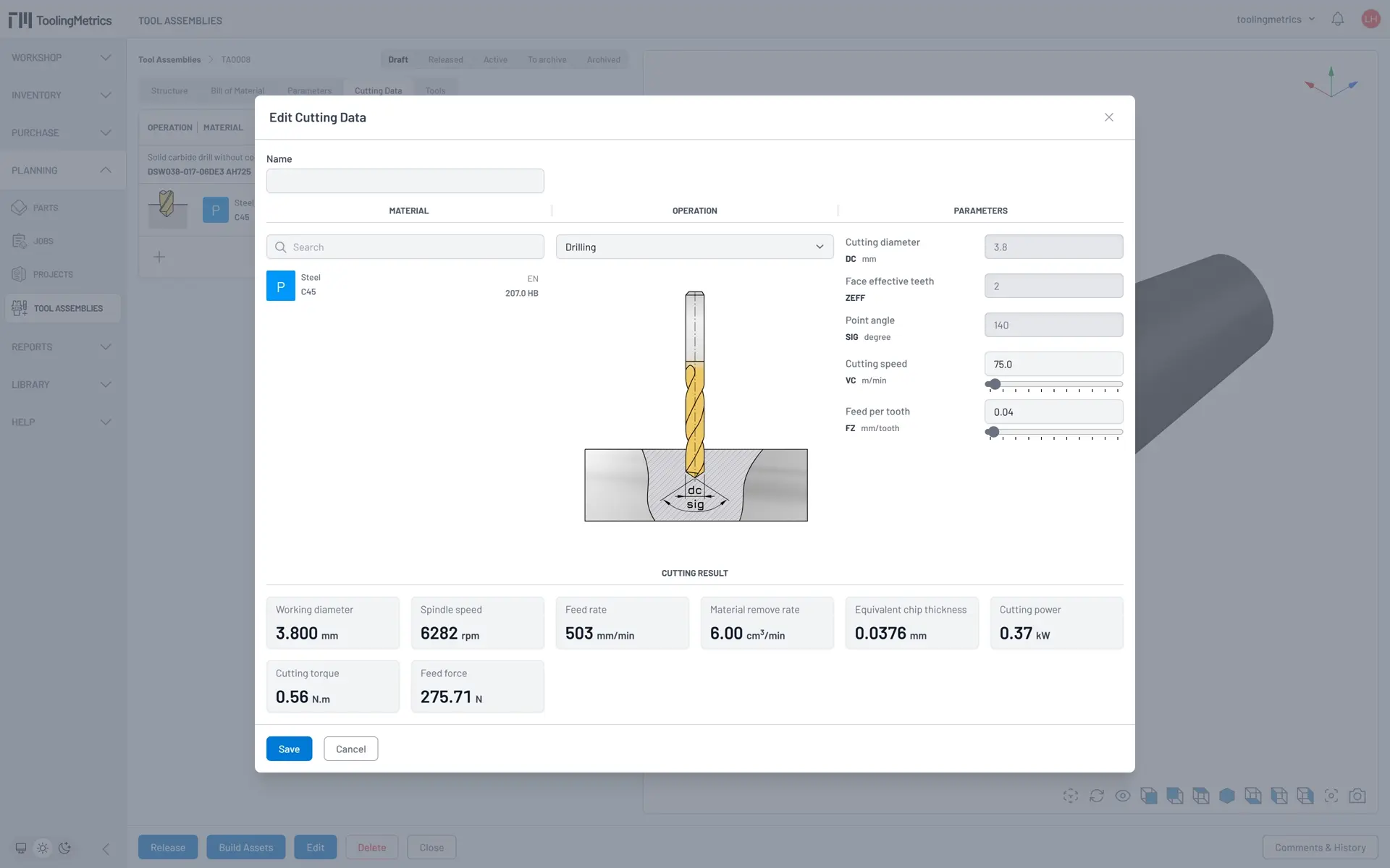
As we specified the operations attribute for the drill product, we only have the drilling operation on the drop down list. Click on the material search box, then type S 45 as the material name. All matches material instantly show up in the result list. Select the material with name is S 45C and hardness is 220 HB for this operation.
The Machining Calculator automatically aggregates all possible cutting parameters from the tool assembly parameters to list on the cutting Parameters column. For our drilling operation, we have DC = 3.5 mm, ZEFF = 2, SIG = 140 degree, and two variable parameters which are VC and FZ.
At the bottom area is the cutting result, derived from the cutting parameters. The cutting result are instantly updated whenever any of the cutting parameters, operation, or material are changed. For now, let’s set the VC = 75 m/min and FZ = 0.04 mm/tooth, then save this cutting data.
At this point, you have your first completed tool assembly. We encourage you to create a few more tool assemblies from different products, and play around with other assembly builder features like reposition, insert, exchange, or delete a assembly node.
Warehouse
We are going to set up a warehouse and create two storage devices to begin managing our inventory. This can only be done by users who are organization admins or site admins.
The following steps provide instructions to create a warehouse and its access point:
- Access the admin center by clicking the current organization menu ➔ Manage Organizations ➔ View your organization detail.
- On the left side of the organization detail view is the admin sidebar. Under the Inventory section, click Warehouses ➔ + New button in the navigation bar.
- Fill in the Name and Delivery address. Select yourself as the Administrator and leave the Parent Warehouse blank. Then click Save to confirm.
- Move the mouse cursor to the admin sidebar and click Warehouse Access Points ➔ + New to create a new one.
- Give it a Name and Description. Select the Warehouse it belongs to, as well as the Administrator, and then click the Save button.
Next, select Storage Devices in the admin sidebar. You will see our storage devices list is empty. Follow the steps below to create a vertical pull-out cabinet for storing completed tools:
- Click the + New button to create a new Storage Device.
- Name it Tools Vertical pull-out cabinet. Select the Administration and the Warehouse access point you created in the previous task. Also, set the Type to Manual, the Up direction to X, and the X, Y Coordinate to 0. Then click Save to create.
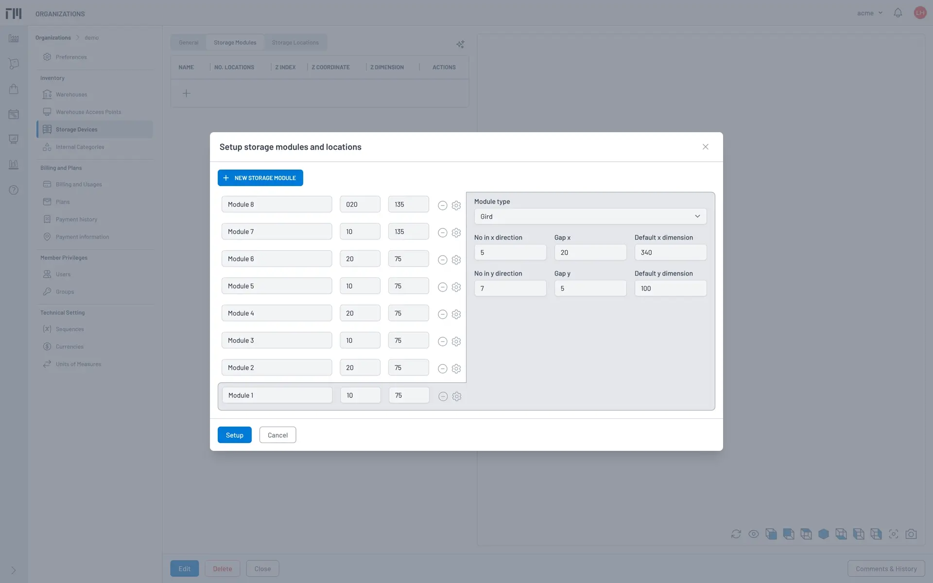
- Find the storage device you just created and open its detail view. You will now see a Setup button on the right of the document tab bar. Click it to open the Setup storage modules and locations dialog.
- Click on the Gear icon to show the Module 1 configuration. Ensure that the Module type is Grid, the values for No in X dimension, Gap X, and Default X dimension are 5, 20, and 340, respectively. The values for the Y axis are 7, 5, and 100.
- Apply the previous configuration for Module 2 through Module 6.
- Click the New Storage Module button to create Module 7 and Module 8. These two modules use the same configuration as before, except the values for the Y axis are 4, 5, and 163.
- Now adjust the Gap and Height of all the modules according to the Fig. 2, then click Setup to generate all modules and locations.
We also need another storage device to keep small tools and individual items like turning holders, inserts, solid tools, micrometers, calipers, etc. The following steps guide you to set up a drawer cabinet for this purpose:
- Follow the steps in previous task to create a new storage device. For this one, set the Up direction to Z, and X, Y Coordinate to 860, 235
- Open the Setup storage modules and locations dialog, and edit the storage modules using the data in the modules configuration table.
- After completing the setup, you can visualize its 3D model by clicking the Reload icon in the CAD toolbar.
| Module name | Module gap | Module dimension | Module type | Gap X | Gap Y | Dimension | Location dimensions |
|---|---|---|---|---|---|---|---|
| Drawer 1 | 25 | 300 | X direction | 0 | 0 | 300 | 600 |
| 0 | 0 | 300 | 150,150,300 | ||||
| Drawer 2 | 25 | 200 | X direction | 0 | 0 | 200 | 150,150,300 |
| 0 | 0 | 200 | 150,150,150,150 | ||||
| 0 | 0 | 200 | 150,150,75,75,75,75 | ||||
| Drawer 3 | 25 | 100 | Y Direction | 0 | 0 | 150 | 150,150,150,150 |
| 0 | 0 | 150 | 150,150,150,150 | ||||
| 0 | 0 | 150 | 75,75,75,75,75,75,75,75 | ||||
| 0 | 0 | 150 | 75,75,75,75,75,75,75,75 | ||||
| Drawer 4 | 25 | 100 | Y Direction | 0 | 0 | 150 | 150,150,150,150 |
| 0 | 0 | 150 | 75,75,75,75,75,75,75,75 | ||||
| 0 | 0 | 150 | 75,75,75,75,75,75,75,75 | ||||
| 0 | 0 | 75 | 75,75,75,75,75,75,75,75 | ||||
| 0 | 0 | 75 | 75,75,75,75,75,75,75,75 | ||||
| Drawer 5 | 0 | 50 | X Direction | 0 | 0 | 50 | 150,75,75,75,75,75,75 |
| 0 | 0 | 50 | 150,75,75,75,75,75,75 | ||||
| 0 | 0 | 50 | 150,75,75,75,75,75,75 | ||||
| 0 | 0 | 50 | 150,75,75,75,75,75,75 | ||||
| 0 | 0 | 50 | 150,75,75,75,75,75,75 | ||||
| 0 | 0 | 50 | 150,75,75,75,75,75,75 | ||||
| 0 | 0 | 50 | 150,75,75,75,75,75,75 | ||||
| 0 | 0 | 50 | 150,75,75,75,75,75,75 | ||||
| 0 | 0 | 50 | 150,150,150,150 | ||||
| 0 | 0 | 50 | 150,150,150,150 | ||||
| 0 | 0 | 50 | 150,150,150,150 | ||||
| 0 | 0 | 50 | 150,150,150,150 |
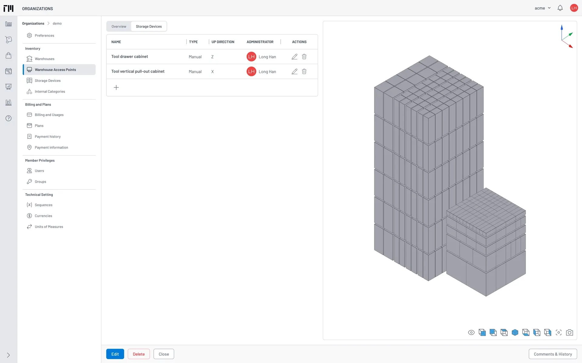
After successfully completing the three tasks above, you can now go to the Warehouse Access Point detail to view its 3D model as shown in the following picture. We will use those storage devices to organize our inventory items in the next section.
Inventory
This section guides you through creating items from the product library and organizing them into categories to configure usage cost methods in an effective way. After that, we will start an initial inventory valuation by counting physical item quantities and costs.
Internal Category
An Internal Category is a tree structure used to organize items. To start managing the organization’s internal categories, you need to access the admin center, then click the Internal Categories icon, which is right below Storage Devices in the admin sidebar. An internal category also allows you to set the Usage cost method and Usage rate for its items. The best practice for categorizing items is based on how their cost is allocated to the production cost.
Creating Internal Categories
- Click + New to open the internal category creation dialog.
- Enter Cutting Tools for the Name. Set the Usage cost method to Fixed Rate and the Usage rate to 0.0
- Click the Save button to confirm the item creation and close the dialog.
-
Repeat these steps to create some Cutting Tools child categories with the usage cost methods and usage rates from the following list:
- Holders: Unit Cost x Usage Rate in Percentage, 0.02
- Inserts: Unit Cost x Usage Rate in Percentage, 1.0
- Solid Tools: Usage Time in Hour x Usage Rate, 0.0
Now you have a basic categories structure ready to create the items.
Configuring Item Synchronization Preferences
Tooling Metrics allows items to be created/updated by synchronizing their data from the product library. Before doing that, we will configure how product attributes are synced with item attributes.
- Move the mouse cursor to the top of the admin sidebar and click on Preferences.
-
Find and make sure the following preferences are set:
- Regional setting ➔ Currency: Set to USD - United States dollar.
- Regional setting ➔ Time zone: Use your local time zone.
- Synchronize Item ➔ Name with product: Here we use the designation for better attributes decode-ability.
- Synchronize Item ➔ Default category: Select Cutting Tools in the select box, so every newly created item will belong to this category.
- Remember to click the Update button at the end of the page to make sure all changed preference values are saved.
Syncing Items from Library
You can sync items individually from a product or sync all items within a tool assembly at once.
Syncing an Individual Item
- Move your mouse cursor to the sidebar and switch the active document to Products.
- Enter SCD 035-014-060 ACP3N into the search box and hit Enter. The products list should now contain only that product designation.
- Click the product picture to open the detail view.
- Click the Sync with Item button to start the sync process. When the process is completed, a success message appears to notify you that an item has been created.
- Click the Close button to close the product detail view.
Syncing Items from a Tool Assembly
- Go to theTool Assemblies list.
- Open the tool assembly named CAT40 Drill 3.8 (which we created in the Tool Library section).
- Click the Release button on the bottom toolbar.
Releasing a tool assembly triggers a job that creates or updates all items in its Bill of Materials. For this tool assembly, a message appears notifying you that the tool assembly has been released, with 2 items created, 1 item updated.
Performing the Initial Inventory Count
Switching to the Items list, you might see 3 items just created in the previous task. Because those items are in stock and ready to use, we will need to init the beginning quantities and valuation to keep tracking it inventory and usages.
Now we will set the starting quantities and values for the items created. The initial inventory quantities and valuation are recorded using an Inventory Adjustment. Make sure you make Inventory Adjustment is the active document before proceeding these steps.
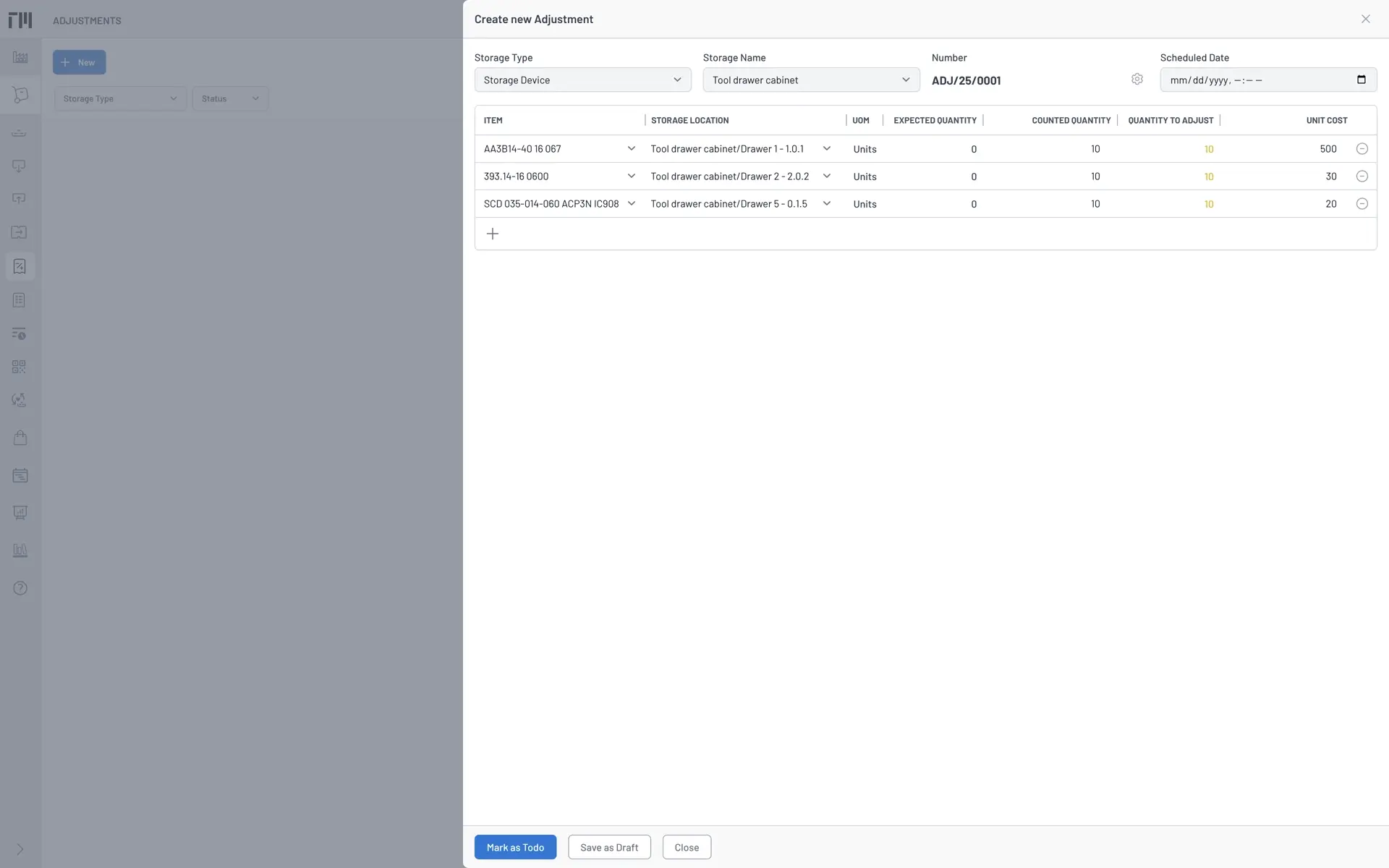
- Click + New to open Create new Adjustment form.
- Select the Storage Type as Storage Device, and the Storage Name as Tool drawer cabinet.
- Click the ⨁ button to add a new adjustment line. We need three adjustment lines with the item, storage location, counted quantity, unit cost of each lines as the Fig. 4.
- Click Mark as Todo to save the Adjustment (number ADJ/25/0001) and mark its status as Ready.
- In the Adjustment detail view open, review all adjustment lines in the Move Lines tab.
- Click the Validate button on the bottom toolbar to confirm the move line details are correct.
After successful validated, you will see the adjustment status change to Done. A success message will also appear, together with a change log entry appended in the document history to track your validation action.
When switching back to the Items list, you can verify that the unit cost and on-hand quantity of those items have been updated to reflect the move lines’ quantity and cost, as well as that the status is Active.
Machines
At this point, our demo organization database contains a small product library, a tool assembly, and an inventory with three items stored inside two storage devices. The last resource we need to initialize in this section is a machine tool. We will employ a 3-axis CNC machining center for our demonstration.
- Click + New to open the Create new Machine form.
- Enter the Name as Haas TM-01, along with the Builder, Model, Serial Number. Set the Warehouse Access Point to the one you created in the warehouse setup task.
- Attach the machine picture and 3D model.
- Click Save to confirm, and you will be directed to its detail view.
We also need to configure the machine components and interfaces, which helps us simplify the tool holder selection when building our tool assemblies. In the machine detail view, follow these steps to configure for our machine spindle is a CAT40 standard.
- Click the Components ➔ ⨁ button to add a new machine component.
- Enter the Name as Spindle, and the No slots as 30. Set the Type to Head, and click Save button.
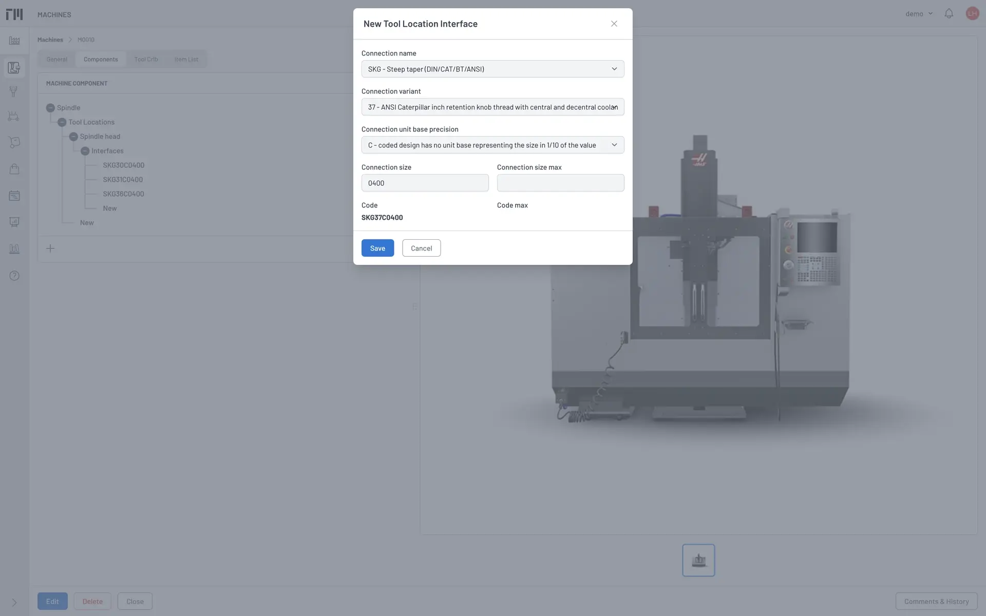
- Open the Spindle component tree and find the New button under Interfaces. Click it to open the New Tool Location Interface dialog.
- Set the interface attributes as shown in Fig. 5 and save this CAT40 (without coolant supply) interface. Verify that the interface code is SKG30C0400 before click the Save button.
- Create other three interfaces with the codes are SKG31C0400, SKG36C0400, and SKG37C0400 like the one you have done.
Now that the machine tool is configured with a CAT40 spindle interface, you can check which tool assemblies in your library are compatible.
- Go to the Tool Assemblies list.
- Select the machine you just created (e.g., Haas TM-01) from the Fit on Machine filters toolbar.
- The results list should then contain only the first tool assembly you have been built.
By completing that last task in this stage, you have completed the initialization of required production resources for our demo project. Well done!
In the next stage, we will use those resources to create job setup instructions and develop an efficient purchase plan for preparing the necessary items and tools, ensuring they are ready to run the job on the machine.
-
[1] Use of this package or products does not imply we have any partnership, affiliation with or endorsement by with its manufacturers. This solely because any registered user can download the package or asset files from their website, so that you can follow this guide without any obstacle. ↩