
We’re excited to release two new features Cutting Data & Machining Calculator, that aim to make the CAM workflow more smoothly. Make it easy to manage cutting data and quickly understand the dynamics relationships between them and machining results. Let talk about the Cutting Data first.
Cutting Data
Cutting data is central place to manage cutting parameters for your Tool Assembly. You can access all the functionalities from the Cutting Data tab, next to the Parameters tab.
Any cutting data have to have one specific workpiece material, and we use that to calculate the specific cutting force kc with Kienzle law. Each cutting parameters set is different when you apply the same tool to difference operations.
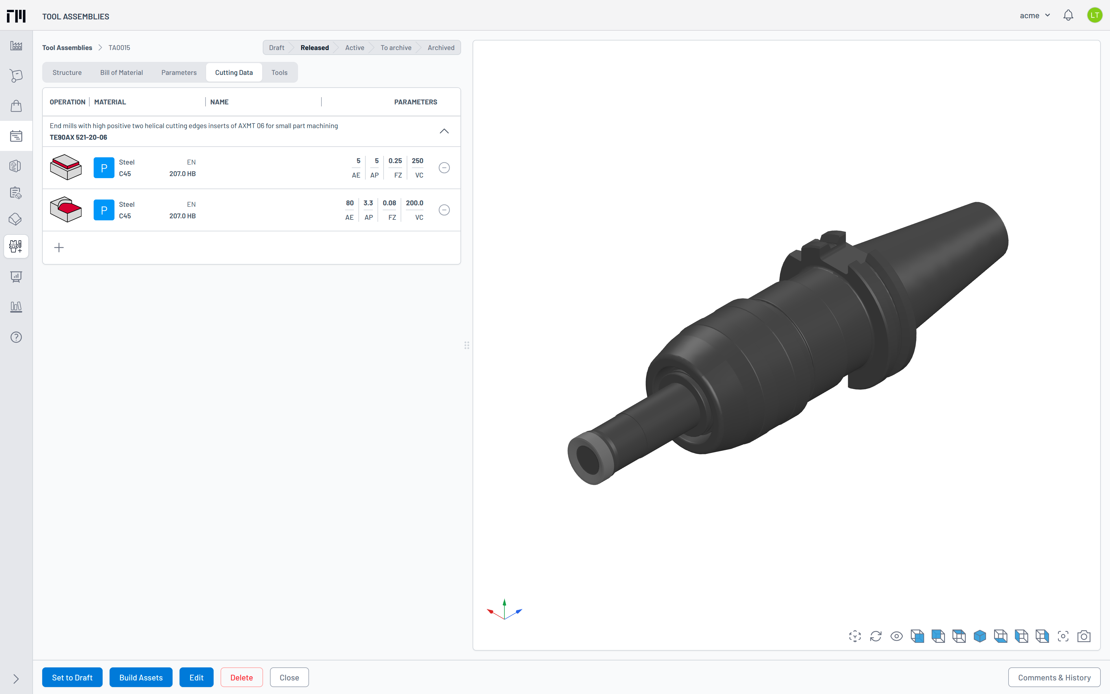
Therefore, we display to those important variable: Operation, Material, and Parameters in table layout, helping you quickly compare between cutting data sets.
Bellow is some highlight & notes:
- Saving cutting parameters directly within the Tool Assembly.
- Automatic fill in cutting parameters from Tool Assembly parameters.
- Allow user to manually fill in the missing required parameters.
- Set the min, max value for each parameter base on the Tool Assembly parameters if possible.
- Cutting data is defined for each tool item. Therefore, multi turn or mill-turn tool class is supported, but if you build your own multi edge boring tool, you should define your cutting data for only one cutting edge. We will look for the way to improve multi-edge boring tool behave in further release.
- Support all machining operation in ISO 13399, which manufacturer have to be defined in the product data file (.p21 file).
- Considering the tool class to define the correct parameters set and/or cutting results i.e. internal threading can be done by either tapping, thread turning, or thread milling operation.
- A simple, but clear illustration for each cutting parameter, in each operation.
- Cutting parameters will be reset to the default value when you changed operation without saving parameters yet.
- Support both Metric & Imperial measurement system. When you switch between the system, the cutting data was saved in other system shows the converted value, and only save with new unit system until you update those one.
Machining Calculator
When you have all required variable i.e. workpiece material, cutting operation, and cutting parameters in placed. The Machining Calculator will calculate the machining results. These cutting result is provided as it is base on the theoretical equations & research model, helping you get the good starting point of the real result at your machine.
Again, bellow is some highlight & notes:
- Easy to search and define workpiece material.
- Instantly & dynamic calculate cutting result when materials, cutting parameters changed.
- Being transparency about how to calculate the cutting result.

Cutting Results
There are two groups of cutting result: one is can be model and calculate only base on the tool class design and parameters like working diameter, speed & feed, material remove rate. Another group which has uncut chip thickness (maximum, average, and equivalent), cutting force/torque, cutting power, tool life, are mainly depend on experiment works.
Working diameter
Working diameter is an obvious parameter for every machinist? The answer is yes, but it’s not simple like you think. Let look at the face milling operation bellow.
If the CAM programmer/operator apply the same spindle speed to difference finishing (ap = 0.15 mm) and roughing operation (ap = 6 mm). The cutting speed changed almost 25%, without his/her attention. According to Taylor, the tool life reduce about 50% when the cutting speed increase about 10%. That is a huge effect!
With our Calculator, he will be got the exactly working diameter in this case, even some complex case is copy milling with tilt angle when he does have a 5-axis machining operation.
Speed & Feeds, Material Remove Rate
Those are the standard in every machining operations. We recommend you should try to maximize feed rate/MRR base on your own criteria, such can be MRR in roughing operation, feed rate in finishing operation or drill/tapping operation.
Uncut Chip Thickness
Uncut chip thickness is an important parameter when design cutting edge, but it’s not in the world of CAM Programmers/Operators. With them, it’s look like feed per tooth. We use equivalent chip thickness instead average or maximum one because it’s given the estimation for cutting force and tool life more accurate. Equivalent chip thickness is not so practical as average/maximum one. It’s complex to calculate, but this is where you make the difference.
Because each cutting edge is designed to cut certain amount of equivalent chip thickness. CAM Programmers/Operators should try to adjust the cutting parameters to take full its capability.
Cutting force/torque and cutting power
In general, we apply the Kienzle law Fc = kc11 x h x b1 - mc to calculate the cutting force, cutting torque, and cutting power depend on machining operation characteristics.
Cutting data could be one of a valuable asset in your machining workshop, your competitive advantaged if you can maximize to improving your machining results. Our aim is giving you a tool to assist that journey. We hope that those cutting results will assist you well to transform your tooling workflow.
Notable improvements
- Assembly Viewer now can display the dimensions in both Metric and Imperial system, base on user preferences setting.
- View Transitions: We have been updated our tech stacked to enable view transitions for reducing your cognitive load, and reducing perceived loading latency as you navigating between pages/views in the application interface. Unfortunately now only the Chrome or Edge browser is supported this feature. Please do take note this if you would to get the best experience with Tooling Metrics.
- GTC Class hierarchy has been update to version 2024.02 which added class icon to some cutting items/adaptive items. We pushed more other meaningful parameters from products parameter to the Assembly parameters, especially is the one having relationships with cutting results like PHD (pre hole diameter) for the drilling and tapping classes.
- Drawing Viewer now added loading spinner.
- Added Created by to Material, Machine, and Part. And the ability to filtering by that.
- Member Privileges: Control the user privileges is now more intuitive as the Group permission for each model can be select from a list with detail permission logic in bellow table:
| Role | View owned | Manage owned | View others | Manage others |
|---|---|---|---|---|
| Admin | ✓ | ✓ | ✓ | ✓ |
| Manager | ✓ | ✓ | ✓ | |
| User | ✓ | ✓ | ||
| Viewer | ✓ | |||
| No permission |
Notable fixes
- Fixed error when Tool Assembly could not be classified.
We love to hear to your feedback to continue developing our platform, and supporting you achieve the sustainable development goals!
ToolingMetrics team